



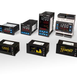



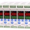

VX series high-performance LCD temperature controller
– High input accuracy and excellent control performance
– Durable plastic key system
– Easy setup and maintenance with 5 keys
– Easy internal replacement by front without reconnecting terminal wires
– Multiple devices can be set in batch without separate input power with the loader communication connection.
– Space saving with the 63 mm short body length
| Model | Code | Description | ||||||||||
|
VX |
|
Digital PID Controller |
||||||||||
|
Size |
2 |
48W x 96H x 62.5D |
||||||||||
|
3 |
96W x 48H x 62.5D |
|||||||||||
|
4 |
48W x 48W x 63D |
|||||||||||
|
7 |
72W x 72W x 62.5D |
|||||||||||
|
9 |
96W x 96W x 62.5D |
|||||||||||
|
Sensor |
U |
Universal Input |
||||||||||
|
Output 1 |
M |
Relay Output |
||||||||||
|
S |
DC Voltage Output for SSR drive) |
|||||||||||
|
C |
DC Current Output (4-20mA) |
|||||||||||
|
Output 2 |
N |
None |
||||||||||
|
M |
Relay Output |
|||||||||||
|
Power Source |
A |
100-240VAC 50/60Hz |
||||||||||
|
D |
24VDC |
|||||||||||
|
Sub Output |
A1 |
1 Relay Output (Basic option for VX4) |
||||||||||
|
A2 |
2 Relay Outputs (Basic Option for VX2, VX7, VX9) |
|||||||||||
|
A4 |
4 Relay Outputs (Option available only for VX2, VX3, VX7, VX9) |
|||||||||||
|
Communication |
C |
RS-485 communication |
||||||||||
|
Retransmisstion output (RET) |
T |
4-20mA Retransmission Output |
||||||||||
|
Digital Input (DI) |
D2 |
2 digital inputs (DI 1 -2) |
||||||||||
|
Current Detection input (CT) |
H1 |
CT coil input, 1 Contact |
||||||||||
|
Remote Input (REM) |
R |
1 input, 4-20mA (1-5V) |
||||||||||
Specifications
| Classification | VX2 | VX3 | VX4 | VX7 | VX9 | ||
| Input | Thermocouple | K, J, E, T, R, B, S, L, N, U, W, PLII | |||||
| Reference junction compensation accuracy |
±1.5 ℃ (within -10~50 ℃) | ||||||
| RTD | JPT100, PT100 | ||||||
| Allowable line resistance | Each 3 wire within 10 Ω (but the resistance among 3 lines should be same) | ||||||
| DC voltage / current | 1 ~ 5 V (4 ~ 20 mA), 0 ~ 5 V, 0 ~ 10 V, 0 ~ 50 mV, 0 ~ 100 mV | ||||||
| Sampling cycle | 50 ms | ||||||
| Control output |
Relay output (OVC II, Resistive load) |
▪ Rated switching capacity : 5 A 240 V a.c., 5 A 30 V d.c. ▪ Max. switching power : 750 VA, 90 W ▪ Max. switching voltage : 240 V a.c., 110 V d.c. ▪ Max. switching current : 5 A ▪ Mechanical life : 20 million times (at 180 CPM) |
|||||
| ▪ VX3 Rated switch capacity: 3 A 240 V a.c. , 3 A 30 V d.c. ▪ maximum switching current: 3 A |
|||||||
| AC voltage type voltage pulse output |
12 V d.c. ± 1 V d.c. pulse voltage (load resistance min. 600 Ω) | ||||||
| DC voltage type voltage pulse output |
12 – 15 V d.c. pulse voltage (load resistance min. 600 Ω) | ||||||
| Current output | 4 ~ 20 mA ± 0.2% of FS ± 1 digit, load resistance: max. 600 Ω | ||||||
| Control | Control type | ON/OFF, PID control, 2DOF PID control | |||||
| Output operation | Reverse action, direct action | ||||||
| Memory | Non-volatile memory life |
EEPROM unlocked: when setting E2P.L: OFF in G.SET group (EEPROM life: 1 million times write guaranteed) / EEPROM locked: when setting E2P.L: ON in G.SET group (store in RAM) |
|||||
| Display part (H*W)mm |
Display method | Wide viewing angle LCD | |||||
| PV character | 20.5 x 6.9 | 19.7 x 7.2 | 15.2 x 6.8 | 19.8 x 9.3 | 29.0 x 13.6 | ||
| SV character | 12.8 x 5.9 | 10.7 x 4.7 | 7.4 x 3.9 | 10.2 x 4.9 | 15.0 x 7.2 | ||
| MV character | 9.3 x 4.4 | 7.3 x 3.5 | 7.4 x 3.9 | 7.5 x 3.3 | 11.0 x 4.8 | ||
| USB Loader |
Communication method |
USB 2.0 | |||||
| Protocol | ▪ Protocol : PC-LINK ▪ Baudrate : 38400 bps ▪ Start bit : 1 bit ▪ Data bit : 8 bit ▪ Parity bit : None ▪ Stop bit : 1 bit |
||||||
| Communication distance |
Within 5 m | ||||||
| Option | Sub output | ▪ Relay 1 ~ 4 outputs ▪ rated switching capacity: 5A 240 V a.c., 5 A 30 V d.c. | |||||
| Digital input | ▪ 2 points or 4 point ▪ Contact input ON : 1 KΩ max., OFF: 100 KΩ min. ▪ Non-contact input ON : 1.5 V max., OFF: 0.1 mA max. ▪ Current Flow : approx. 2 mA per contact, Voltage at open : Approx. 5 V d.c. |
||||||
| Retransmission output |
▪ 1 output ▪ 4 ~ 20 mA ± 0.2% of FS ± 1 digit ▪ load resistance: max. 600 Ω | ||||||
| Remote input | ▪ 1 input ▪ 4 ~ 20 mA (1 ~ 5 V) | ||||||
| Current detection input |
▪ 1 input or 2 inputs ▪ 0.0 – 50.0 A ▪ CT-70 current transformer (sold separately) | ||||||
| RS-485 | Communic method |
▪ EIA RS485 standard ▪ 2-wire half-duplex | |||||
| Max. connections |
31 (address setting 1~99 available) | ||||||
| Communic sequence |
No sequence | ||||||
| Communic distance |
Within 1.2 ㎞ | ||||||
| Communic speed |
4800, 9600, 14400, 19200, 38400, 57600 BPS | ||||||
| bit | ▪ Start bit : 1 bit ▪ Data bit : 7 or 8 bit ▪ Parity bit : NONE / EVEN / ODD ▪ Stop bit : 1 or 2 bit |
||||||
| Protocol | ▪ PC-LINK STD ▪ PC-LINK WITH SUM ▪ MODBUS-ASCII ▪ MODBUS-RTU | ||||||
| Response time |
Actual response time = processing time + (response time X 50 ㎳) | ||||||
| Power | AC Power Supply Voltage |
100 – 240 V a.c., 50/60 Hz | |||||
| DC Power Supply Voltage |
24 V d.c. , Class2 | ||||||
| Voltage fluctuation rate |
±10 % of power voltage | ||||||
| Insulation resistance |
Min. 20 MΩ, 500 V d.c. | ||||||
| Dielectric strength |
▪ 3,000 V a.c. ▪ 50/60 Hz for 1 minute (between 1st and 2nd terminal) | ||||||
| AC voltage type power consumption |
Max. 8.5 VA | Max. 8.5 VA | Max. 8.2 VA | Max. 8.5 VA | Max. 9.0 VA | ||
| DC voltage type power consumption |
Max. 2.7 W | Max. 2.7 W | Max. 2 W | Max. 2.8 W | Max. 3.2 W | ||
| Ambient temperature & humidity |
-10 ~ 50 ℃, 35 ~ 85 % RH (without condensation) | ||||||
| Storage temperature | -25 ~ 65 ℃ | ||||||
| Approval |  |
||||||
| ▪ Electrostatic discharge (ESD) : KN61000-4-2 ▪ EFT(RS) : KN61000-4-3 ▪ Conductive RF (CS) : KN61000-4-6 ▪ SURGE : KN61000-4-5 |
|||||||
| IP65 (front panel) |
IP65 (front panel) |
IP66 (front panel) |
IP65 (front panel) |
IP65 (front panel) |
|||
| Weight | 202g | 202g | 120g | 194g | 290g | ||
| Basic components | Main body, Bracket, 250 Ω resistor (1%) , Rubber packing, Instruction manual | ||||||


